SysRS: System Requirements Specification
| ID | Type | Source | Description | Comments | Verification Method | Compliance | Justification Level | Justification document | Links | Discussion |
|---|---|---|---|---|---|---|---|---|---|---|
| SysRS-1 | Section |
1 Functional Requirements |
Compliant | None | ||||||
| SysRS-2 | Functional |
All functional requirements shall be captured and documented using MBSE ARCADIA method. |
• Review of Design |
Compliant | Preliminary | eVECTORS Capella model | ||||
| SysRS-3 | Functional |
Capella MBSE Software version 5.1 shall be used |
• Review of Design |
Compliant | Complete | eVECTORS Capella model | ||||
| SysRS-13 | Functional |
The vehicle shall accommodate driver with anthropometric dimension within 10% percentil to 90% percentil of European population |
• Review of Design |
Compliant | Preliminary | |||||
| SysRS-5 | Section |
2 Interface Requirements |
Compliant | Preliminary | ||||||
| SysRS-6 | Interface |
The location in space of any eVECTORS item shall be specified using the different coordinate systems defined in document eVEC-SPEC-002 |
• Review of Design |
Compliant | Preliminary | |||||
| SysRS-7 | Section |
3 Standards and Normative Requirements |
Partially Compliant | Preliminary | ||||||
| SysRS-9 | From Standard |
The vehicle shall be compliant with all Swiss Regulation applicable to category L5e-A. |
Partially Compliant | Preliminary | ||||||
| SysRS-18 | Information |
Note that this preliminary specification is not exhaustive. The latest applicable Regulation shall be followed. In this document, only the key requirements that were taken into account for the development of the prototype are listed. |
Non Compliant | None | ||||||
| SysRS-10 | Section |
3.1 Requirements derived from EU 168/2013 |
Compliant | Preliminary | ||||||
| SysRS-11 | From Standard | EU 168/2013, art 2 |
The driver shall have a R-point higher than 400 mm |
• Review of Design |
Compliant | Preliminary | CAD |
References:
Glossary-2 or ‘seating reference point’ means a des…
|
||
| SysRS-8 | From Standard | EU 168/2013, art 5 |
The vehicle mass in running order shall be lower than 1000 kg |
The requirement for category L2e - Three-wheel (<45 km/h) moped is 270 kg. It is thus a "nice to have" to be under 270 kg. |
• Inspection • Review of Design |
Compliant | Preliminary |
References:
Glossary-4 The mass in running order of an L-catego…
|
||
| SysRS-14 | From Standard | EU 168/2013, art 5 |
The vehicle shall support the driver mass of 75 kg |
Compliant | None | |||||
| SysRS-15 | From Standard | EU 168/2013, art 20 |
The vehicle powertrain shall be protected to prevent modification that may prejudice safety, in particular by increasing vehicle performance through tempering with the powertrain in order to increase the maximum torque and/or power and/or maximum design vehicle speed which have been duly established during the type-approval procedure as followed by the manufacturer of the vehicle; and/or to prevent damage to the environment |
• Inspection • Review of Design |
Non Compliant | None | ||||
| SysRS-16 | From Standard | EU 168/2013, art 21 |
The vehicles shall be equipped with an OBD system which complies with the functional requirements and test procedures as laid down in the delegated acts adopted pursuant to paragraph 5 and as from the application dates as set out in Annex IV of EU Regulation 168/2013. |
• Test • Review of Design |
Non Compliant | None |
References:
Glossary-5 ‘on-board diagnostic system’ or ‘OBD sys…
|
|||
| SysRS-17 | From Standard | EU 168/2013, art 24 |
Electric energy consumption and electric range shall be either calculated based on the type-approval emission laboratory test results or measured, witnessed by the technical service and reported to the approval authority. |
• Analysis • Test |
Compliant | None | ||||
| SysRS-19 | From Standard | EU 168/2013, Annex I |
The vehicle shall have the following maximal dimensions: |
The maximal dimension required for L classification are: length: 4m, width: 2m, height: 2.5 m |
• Inspection • Review of Design |
Compliant | Preliminary | |||
| SysRS-20 | From Standard | EU 168/2013, Annex I |
The vehicle maximum continuous rated power shall be smaller than 15 kW |
The standard is not restrictive for L5e. The limt for L7e has been taken here. |
• Test |
Compliant | Preliminary |
References:
Glossary-6 the maximum thirty minutes power at the …
|
||
| SysRS-21 | From Standard | EU 168/2013, Annex II |
The vehicle shall be compliant with electromagnetic compatibilty requirements defined in CEE-ONU Regulation No 10. |
• Analysis • Test • Inspection • Review of Design |
Non Compliant | None | ||||
| SysRS-22 | From Standard | EU 168/2013, art 23 & 24 - Annex II |
The vehicle sound emission shall be below 80 dB(A), and shall be tested according to UNECE regulation No 9 |
• Test |
Compliant | None | ||||
| SysRS-144 | From Standard | EU 168/2013, Annex II |
The vehicle shall be fitted with a audible warning device |
a Horn |
Compliant | None | ||||
| SysRS-23 | Section |
3.2 Requirements derived from EU 3/2014 |
Non Compliant | None | ||||||
| SysRS-156 | From Standard | EU 3/2014, art 12 |
3.2.1 Driver-operated controls and indicatorsThe vehicle shall respect Annex VIII of Regulation EU 3-2014 regarding driver-operated controls including identification of controls, tell-tales and indicators |
Non Compliant | None | |||||
| SysRS-157 | From Standard | EU 3/2014, Annex VIII, 1.1.3 |
L2e and L5e vehicles must comply with the requirements of points 2 to 2.2.1.6 of Regulation EU 3/2014 Annex VIII or, alternatively, with the requirements of CEE-ONU Regulation No 121 applicable to M1 vehicles. |
• Test • Inspection • Review of Design |
Non Compliant | None | ||||
| SysRS-158 | From Standard | EU 3/2014, Annex VIII, 1.2.1 |
The vehicle must be fitted with a speedometer that complies with CEE-ONU Regulation No 39 and an odometer. |
• Inspection • Review of Design |
Non Compliant | None | ||||
| SysRS-160 | From Standard | EU 3/2014, Annex VIII, 2.1.10 |
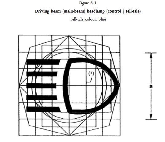
The vehicle shall be fitted with one high beam (driving beam) indicator of blue colour. The symbol shall comply with figure 8.1 |
• Inspection • Review of Design |
Non Compliant | None | ||||
| SysRS-161 | From Standard | EU 3/2014, Annex VIII, 2.1.10 |
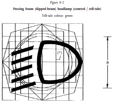
The vehicle shall be fitted with one low beam (passing beam) indicator of green colour. The symbol shall comply with figure 8.2 |
• Inspection • Review of Design |
Non Compliant | None | ||||
| SysRS-162 | From Standard | EU 3/2014, Annex VIII, 2.1.10 |
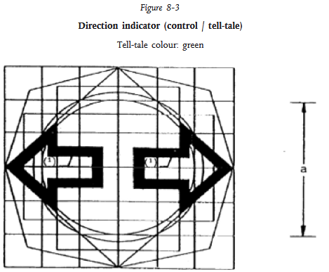
The vehicle shall be fitted with one flashing direction indicator of green colour. The symbol shall comply with figure 8.3. |
• Inspection • Review of Design |
Non Compliant | None | ||||
| SysRS-163 | From Standard | EU 3/2014, Annex VIII, 2.1.10 |
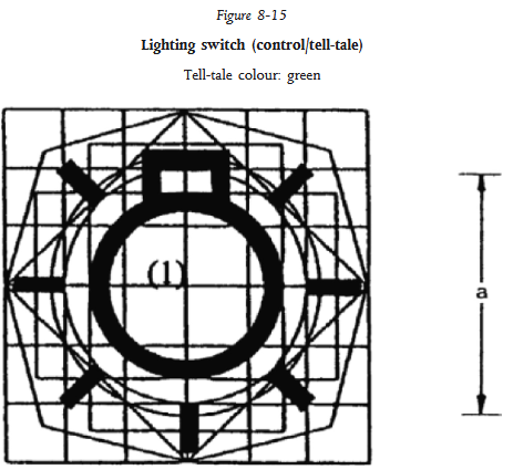
The vehicle shall be fitted with one position light indicator of green colour. The symbol shall comply with figure 8.15 |
• Inspection • Review of Design |
Non Compliant | None | ||||
| SysRS-164 | From Standard | EU 3/2014, Annex VIII, 2.1.10 |
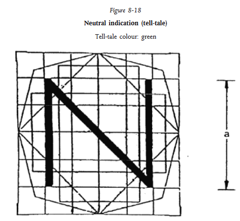
he vehicle shall be fitted with one neutral gear indicator of green colour. The symbol shall comply with figure 8.18 |
Non Compliant | None | |||||
| SysRS-165 | From Standard | ISO 6727:2021 MG.01 |
The vehicle shall be fitted with one reverse gear indicator of green colour. The symbol shall comply with figure MG.01. |
• Inspection • Review of Design |
Non Compliant | None | ||||
| SysRS-166 | From Standard | ISO 6727:2021 MG.03 |
The vehicle shall be fitted with one drive gear indicator of green colour. The symbol shall comply with figure MG.03. |
Non Compliant | None | |||||
| SysRS-167 | From Standard | ISO 2575:2021 H.01 |
|
Non Compliant | None | |||||
| SysRS-168 | From Standard | ISO 2575:2021 M.07 |
The vehicle shall be fitted with one gauge indicating the state of charge of the propulsion battery. The gauge shall be identified with symbol of figure M.07 |
Non Compliant | None | |||||
| SysRS-169 | Functional |
The vehicule shall be fitted with a range indicator (symbol not specified). |
• Inspection • Review of Design |
Non Compliant | None | |||||
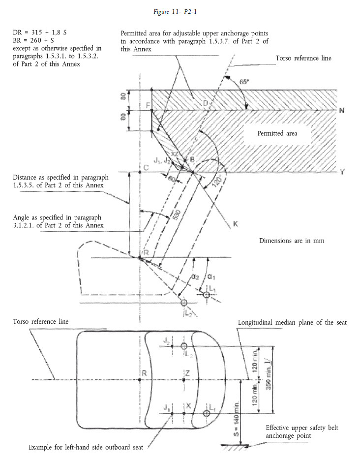
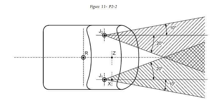
| SysRS-170 | From Standard | ISO 2575:2021 P.08 |
The vehicle shall be fitted with one gauge indicating the malfunction or failure of one system preventing operation of the vehicle. The gauge shall be identified with symbol of figure P.08 |
Non Compliant | None | |||||
| SysRS-171 | From Standard | ISO 2575:2021 P.07 |
The vehicle shall be fitted with one gauge indicating call for maintenance of one or several systems. The gauge shall be identified with symbol of figure P.07 |
Non Compliant | None | |||||
| SysRS-53 | From Standard | EU 3/2014, art 13 |
3.2.2 Lighting and light signalling devicesThe vehicle shall be equipped with lighting and light-signalling devices in accordance with Annex IX of Regulation EU 3-2014. |
• Test • Review of Design |
Compliant | Preliminary | CAD | |||
| SysRS-55 | From Standard | EU 3/2014, Annex IX, 2.1.10 |
The electrical connections shall be such that the front position lights, rear position lights and rear number plate lights can only be switched on and off simultaneously. |
• Review of Design |
Compliant | None | ||||
| SysRS-54 | From Standard | EU 3/2014, Annex IX, 2.1.11 |
The vehicle shall be equipped with either daytime running lights or low beam headlights that are switched on via the vehicle's main switch. |
• Review of Design |
Compliant | None | ||||
| SysRS-57 | From Standard | EU 3/2014, Annex IX, 2.1.12 |
Electrical connections shall be such that the high beam headlights, low beam headlights and fog lights can only be switched on if the position lights are also switched on. An exception is made in cases where the lights in question are used as a visual warning signal by means of brief activation. |
• Review of Design |
Compliant | None | ||||
| SysRS-58 | From Standard | EU 3/2014, Annex IX, 2.2.4 |
The vehicle shall be equipped with the following lighting devices :
|
Those are required for L5e and L7e vehicles, the list is different for L2e vehicles. |
• Review of Design |
Compliant | Preliminary | CAD | ||
| SysRS-59 | From Standard | EU 3/2014, Annex IX, 2.2.5 |
The vehicle can be equipped with the following devices :
|
Those are authorized for L5e and L7e vehicles, the list is different for L2e vehicles. |
• Review of Design |
Not Applicable | None | |||
| SysRS-60 | From Standard | EU 3/2014, Annex IX, 2.2.6 |
Other than those referred to in eVECTORS-SysRS-58 and eVECTORS-SysRS-59, no lighting or light-signalling devices may be fitted to the vehicle. |
Refers to L5e and L7e only |
• Review of Design |
Compliant | Preliminary | CAD | ||
| SysRS-61 | From Standard | EU 3/2014, Annex IX, 2.2.7 |
Only lighting and light-signalling devices that are approved for category L vehicles may be fitted to the vehicle. However, lighting and light-signalling devices that are approved for fitting to vehicles of categories M1 and N1 in accordance with CEE-ONU n°48 may also be fitted. |
• Review of Design |
Not Applicable | None | ||||
| SysRS-62 | From Standard | EU 3/2014, Annex IX, 2.3.1 |
3.2.2.1 High beam headlightsHigh beam headlights shall comply with the requirements listed in point 2.3.1 of Annex IX (EU 3/2014) |
• Review of Design |
Compliant | Preliminary | ||||
| SysRS-63 | From Standard | EU 3/2014, Annex IX, 2.3.1.1 |
If the vehicle's width exceeds 1.3 m, it must have two high-beam headlights. If the width is smaller than this, one light is sufficient. |
2 lights are implemented |
• Review of Design |
Compliant | Preliminary | CAD | ||
| SysRS-64 | From Standard | EU 3/2014, Annex IX, 2.3.1.3 |
If the vehicle has one only high beam headlight, it must be centred or positioned on either side of the vehicle's median plane with another light If the vehicle has two high beam headlights, they must be mounted symmetrically in relation to the vehicle's median plane |
• Review of Design |
Not Applicable | None | ||||
| SysRS-65 | From Standard | EU 3/2014, Annex IX, 2.3.1.3 |
In the case of a single independent high beam headlight, the distance between the edge of the light-emitting surface and that of a single independent low beam headlight must not exceed 200 mm. |
• Review of Design |
Not Applicable | None | ||||
| SysRS-67 | From Standard | EU 3/2014, Annex IX, 2.3.1.3 |
High beam headlights must be positioned at the front of the vehicle and point forwards. |
• Inspection • Review of Design |
Compliant | Preliminary | CAD | |||
| SysRS-66 | From Standard | EU 3/2014, Annex IX, 2.3.1.4 |
The light exit surface must be visible within a divergent space of 5° from the reference axis of the illuminating surface. |
• Test • Review of Design |
Compliant | None | ||||
| SysRS-68 | From Standard | EU 3/2014, Annex IX, 2.3.1.6 |
All high beam headlights must switch on and off simultaneously. All high beam headlights must switch on when the lighting mode changes from low beam headlight to high beam headlight and vice versa. Low beam headlights may remain on at the same time as the high beam headlights. |
• Inspection • Review of Design |
Compliant | None | ||||
| SysRS-69 | From Standard | EU 3/2014, Annex IX, 2.3.1.7 |
The engagement indicator for high beam headlights is mandatory and must be blue and non-flashing. |
• Inspection • Review of Design |
Compliant | None | ||||
| SysRS-70 | From Standard | EU 3/2014, Annex IX, 2.3.1.8 |
The value of the maximum combined intensity of all main-beam headlamps that may be lit simultaneously is 430 000 cd |
• Test • Review of Design |
Compliant | None | ||||
| SysRS-71 | From Standard | EU 3/2014, Annex IX, 2.3.2 |
3.2.2.2 Low beam headlightsLow beam headlights shall comply with the requirements listed in point 2.3.2 of Annex IX (EU 3/2014) |
• Review of Design |
Compliant | Preliminary | ||||
| SysRS-72 | From Standard | EU 3/2014, Annex IX, 2.3.2.1 |
If the vehicle's width exceeds 1.3 m, it must have two low beam headlights. If the width is smaller than this, one light is sufficient. |
2 lights are implemented |
• Review of Design |
Compliant | Preliminary | CAD | ||
| SysRS-73 | From Standard | EU 3/2014, Annex IX, 2.3.2.3 |
If the vehicle has one only low beam headlight, it must be centred or positioned on either side of the vehicle's median plane with another light If the vehicle has two low beam headlights, they must be mounted symmetrically in relation to the vehicle's median plane |
• Review of Design |
Not Applicable | None | ||||
| SysRS-74 | From Standard | EU 3/2014, Annex IX, 2.3.2.3 |
If there are two low beam headlights, the lateral distance between the outer edges of the light-emitting surfaces and the outer edges of the vehicle must not exceed 400 mm. |
• Inspection • Review of Design |
Compliant | Preliminary | CAD | |||
| SysRS-75 | From Standard | EU 3/2014, Annex IX, 2.3.2.3 |
Low beam headlights must be positioned between 0.5 m and 1.2 m above the ground. |
• Inspection • Review of Design |
Compliant | Preliminary | CAD | |||
| SysRS-76 | From Standard | EU 3/2014, Annex IX, 2.3.2.3 |
In the case of a single independent low beam headlight, the distance between the edge of the light-emitting surface and that of a single independent high beam headlight must not exceed 200 mm. |
• Inspection • Review of Design |
Not Applicable | None | ||||
| SysRS-78 | From Standard | EU 3/2014, Annex IX, 2.3.2.3 |
Low beam headlights must be positioned at the front of the vehicle and point forwards. |
• Inspection • Review of Design |
Compliant | Preliminary | CAD | |||
| SysRS-77 | From Standard | EU 3/2014, Annex IX, 2.3.2.4 |
Geometric visibility relative to the reference axis: - 15° upwards, 10° downwards - 45° on both sides if there is only one light - 45° outwards and 10° inwards if there are two lights |
• Test • Review of Design |
Compliant | None | ||||
| SysRS-79 | From Standard | EU 3/2014, Annex IX, 2.3.2.6 |
All low beam headlights must switch on and off simultaneously. All low beam headlights must switch on when the lighting mode changes from high beam headlight to low beam headlight and vice versa. Low beam headlights may remain on at the same time as the high beam headlights. |
• Inspection • Review of Design |
Compliant | None | ||||
| SysRS-80 | From Standard | EU 3/2014, Annex IX, 2.3.2.7 |
The engagement indicator for low beam headlights is optional and must be green and non-flashing. |
To be decided if implemented or not. TBC |
• Review of Design |
Compliant | None | |||
| SysRS-81 | From Standard | EU 3/2014, Annex IX, 2.3.2.8 |
Adjustment of the initial vertical inclination of the low beam headlights according to the position of the lowest point of the illuminating surface: - below 0.8 m, orientation between -1% and -1.5% - between 0.8 m and 1.0 m, orientation between -1% and -2% - above 1.0 m, orientation between -1.5% and -2% |
• Review of Design |
Non Compliant | None | ||||
| SysRS-82 | From Standard | EU 3/2014, Annex IX, 2.3.2.8 |
Limit for the vertical inclination (in any condition) depending on the initial vertical inclination: - between -0.5% and -2.5% for an initial setting between -1.0 and -1.5% - between -1.0% and -3.0% for an initial setting between -1.5 and -2.0% An adjustment device may be used to meet these requirements: - for an objective luminous flux of less than 2000 lm, the device may be external and require tools supplied with the vehicle - for an objective luminous flux of more than 2000 lm, the device must be accessible to the driver, must be automatic and must have a response time of less than 30 seconds. |
• Test • Review of Design |
Non Compliant | None | ||||
| SysRS-83 | From Standard | EU 3/2014, Annex IX, 2.3.3 |
3.2.2.3 Front position lightsFront position lights shall comply with the requirements listed in point 2.3.3 of Annex IX (EU 3/2014) |
• Review of Design |
Non Compliant | None | ||||
| SysRS-84 | From Standard | EU 3/2014, Annex IX, 2.3.3.1 |
If the vehicle's width exceeds 1.3 m, it must have two front position lights. If the width is smaller than this, one light is sufficient. |
• Review of Design |
Non Compliant | None | ||||
| SysRS-85 | From Standard | EU 3/2014, Annex IX, 2.3.3.3 |
If the vehicle has one only front position light, it must be centered or positioned on either side of the vehicle's median plane with another light. If the vehicle has two front position lights, they must be mounted symmetrically in relation to the vehicle's median plane. |
• Review of Design |
Non Compliant | None | ||||
| SysRS-86 | From Standard | EU 3/2014, Annex IX, 2.3.3.3 |
If there are two front position lights, the lateral distance between the outer edges of the light-emitting surfaces and the outer edges of the vehicle must not exceed 400 mm. |
• Inspection • Review of Design |
Non Compliant | None | ||||
| SysRS-87 | From Standard | EU 3/2014, Annex IX, 2.3.3.3 |
Front position lights must be positioned between 0.35 m and 1.2 m above the ground. |
• Review of Design |
Non Compliant | None | ||||
| SysRS-88 | From Standard | EU 3/2014, Annex IX, 2.3.3.3 |
Front position lights must be positioned at the front of the vehicle and point forwards. |
• Review of Design |
Non Compliant | None | ||||
| SysRS-89 | From Standard | EU 3/2014, Annex IX, 2.3.3.4 |
Geometric visibility relative to the reference axis: - 15° upwards, 15° downwards; can be reduced to 5° downwards if the light is lower than 0.75 m from the ground - 80° on both sides if there is only one light - 80° outwards and 45° inwards if there are two lights |
• Review of Design |
Non Compliant | None | ||||
| SysRS-90 | From Standard | EU 3/2014, Annex IX, 2.3.3.7 |
The engagement indicator for position lights is mandatory and must be green and non-flashing. |
• Review of Design |
Non Compliant | None | ||||
| SysRS-91 | From Standard | EU 3/2014, Annex IX, 2.3.6 |
3.2.2.4 IndicatorsIndicators shall comply with the requirements listed in point 2.3.6 of Annex IX (EU 3/2014) |
• Review of Design |
Non Compliant | None | ||||
| SysRS-92 | From Standard | EU 3/2014, Annex IX, 2.3.6.1 |
The vehicle must have two indicators. Two side indicators may be added as an option and must comply with the requirements of CEE-ONU Regulation No. 48. |
• Review of Design |
Non Compliant | None | ||||
| SysRS-93 | From Standard | EU 3/2014, Annex IX, 2.3.6.2 |
The vehicule shall have two front indicators pointing forwards and two rear indicators pointing backwards |
• Review of Design |
Non Compliant | None | ||||
| SysRS-94 | From Standard | EU 3/2014, Annex IX, 2.3.6.3 |
The inner edges of the light-emitting surfaces of the front indicators must be at least 500 mm apart in the case of vehicles with more than one front wheel. The inner edges of the light-emitting surfaces of the rear indicators must be at least 500 mm apart if the width of the vehicle exceeds 1 000 mm. |
• Review of Design |
Non Compliant | None | ||||
| SysRS-95 | From Standard | EU 3/2014, Annex IX, 2.3.6.3 |
Minimum distance between the light-emitting surfaces of an indicator and a low beam headlight: - 75 mm for a minimum indicator intensity of 90 cd - 40 mm for a minimum indicator intensity of 175 cd - 20 mm for a minimum indicator intensity of 250 cd - <20 mm for a minimum indicator intensity of 400 cd |
• Review of Design |
Non Compliant | None | ||||
| SysRS-96 | From Standard | EU 3/2014, Annex IX, 2.3.6.3 |
Indicators must be positioned between 0.5 m and 1.5 m above the ground. |
• Review of Design |
Non Compliant | None | ||||
| SysRS-97 | From Standard | EU 3/2014, Annex IX, 2.3.6.4 |
Geometric visibility relative to the reference axis: - 15° upwards, 15° downwards; can be reduced to 5° downwards if the light is lower than 0.75 m from the ground - 80° outwards and 45° inwards |
• Review of Design |
Non Compliant | None | ||||
| SysRS-98 | From Standard | EU 3/2014, Annex IX, 2.3.6.6 |
The indicators' switch must be independant from that of other lights. All the indicators located on the same side of the vehicle are switched on and off by the same control. |
• Review of Design |
Non Compliant | None | ||||
| SysRS-99 | From Standard | EU 3/2014, Annex IX, 2.3.6.7 |
The engagement indicator for indicators is mandatory and can be optical or audible or both. If optical, it must be green and flashing. If a front or rear indicator malfunctions, it must remain off, remain on without flashing or show a marked change in frequency. If it is entirely audible, it must be clearly audible and provide information on the same operating conditions as the optical indicator. |
• Review of Design |
Non Compliant | None | ||||
| SysRS-100 | From Standard | EU 3/2014, Annex IX, 2.3.6.8 |
The light must flash 90 ± 30 times per minute. |
• Review of Design |
Non Compliant | None | ||||
| SysRS-101 | From Standard | EU 3/2014, Annex IX, 2.3.6.8 |
The indicators on the same side of the vehicle must flash at the same frequency, in phase, and the flashing may be synchronous or alternating. |
• Review of Design |
Non Compliant | None | ||||
| SysRS-102 | From Standard | EU 3/2014, Annex IX, 2.3.6.8 |
The first flash of the indicator must appear within one second and go out within one and a half seconds of the command being activated. |
• Review of Design |
Non Compliant | None | ||||
| SysRS-103 | From Standard | EU 3/2014, Annex IX, 2.3.6.8 |
In the event of a failure, other than a short-circuit, of a front or rear indicator, the other indicators of the same direction must remain on or continue to flash; however, in such a case, the flashing frequency must not correspond to the value prescribed. |
• Review of Design |
Non Compliant | None | ||||
| SysRS-104 | From Standard | EU 3/2014, Annex IX, 2.3.8 |
3.2.2.5 Rear position lightsRear position lights shall comply with the requirements listed in point 2.3.8 of Annex IX (EU 3/2014) |
• Review of Design |
Non Compliant | None | ||||
| SysRS-105 | From Standard | EU 3/2014, Annex IX, 2.3.8.1 |
If the vehicle's width exceeds 1.3 m, it must have two rear position lights. If the width is smaller than this, one light is sufficient. |
• Review of Design |
Non Compliant | None | ||||
| SysRS-106 | From Standard | EU 3/2014, Annex IX, 2.3.8.3 |
If the vehicle has one only rear position light, it must be centered on the vehicle's median plane. If the vehicle has two rear position lights, they must be mounted symmetrically in relation to the vehicle's median plane. |
• Review of Design |
Non Compliant | None | ||||
| SysRS-107 | From Standard | EU 3/2014, Annex IX, 2.3.8.3 |
Rear position lights must be positioned between 0.25 m and 1.5 m above the ground. |
• Review of Design |
Non Compliant | None | ||||
| SysRS-108 | From Standard | EU 3/2014, Annex IX, 2.3.8.3 |
Rear position lights must be positioned at the back of the vehicle and point backwards. |
• Review of Design |
Non Compliant | None | ||||
| SysRS-109 | From Standard | EU 3/2014, Annex IX, 2.3.8.4 |
Geometric visibility relative to the reference axis: - 15° upwards, 15° downwards; can be reduced to 5° downwards if the light is lower than 0.75 m from the ground - 80° on both sides if there is only one light - 80° outwards and 45° inwards if there are two lights |
• Review of Design |
Non Compliant | None | ||||
| SysRS-110 | From Standard | EU 3/2014, Annex IX, 2.3.8.7 |
The engagement indicator for position lights is mandatory and must be green and non-flashing. |
• Review of Design |
Non Compliant | None | ||||
| SysRS-111 | From Standard | EU 3/2014, Annex IX, 2.3.9 |
3.2.2.6 Stop lightsStop lights shall comply with the requirements listed in point 2.3.9 of Annex IX (EU 3/2014) |
• Review of Design |
Non Compliant | None | ||||
| SysRS-112 | From Standard | EU 3/2014, Annex IX, 2.3.9.1 |
If the vehicle's width exceeds 1.3 m, it must have two stop lights. If the width is smaller than this, one light is sufficient. One more optional stop light mounted in a high centered position (S3 or S4 category) is allowed. |
• Review of Design |
Non Compliant | None | ||||
| SysRS-113 | From Standard | EU 3/2014, Annex IX, 2.3.9.3 |
If the vehicle has one only stop light, it must be centered on the vehicle's median plane. If the vehicle has two stop lights, they must be mounted symmetrically in relation to the vehicle's median plane. |
• Review of Design |
Non Compliant | None | ||||
| SysRS-114 | From Standard | EU 3/2014, Annex IX, 2.3.9.3 |
Minimum distance between the inner edges of the light exit surfaces : - 600 mm for a vehicle wider than 1.3 m - 400 mm for a vehicle less than 1.3 m wide |
• Review of Design |
Non Compliant | None | ||||
| SysRS-115 | From Standard | EU 3/2014, Annex IX, 2.3.9.3 |
Stop lights must be positioned between 0.25 m and 1.5 m above the ground. |
• Review of Design |
Non Compliant | None | ||||
| SysRS-116 | From Standard | EU 3/2014, Annex IX, 2.3.9.3 |
Stop lights must be positioned at the back of the vehicle and point backwards. |
• Review of Design |
Non Compliant | None | ||||
| SysRS-117 | From Standard | EU 3/2014, Annex IX, 2.3.9.4 |
Geometric visibility relative to the reference axis: - 15° upwards, 15° downwards; can be reduced to 5° downwards if the light is lower than 0.75 m from the ground - 45° on both sides if there is only one light - 45° outwards and 10° inwards if there are two lights |
• Review of Design |
Non Compliant | None | ||||
| SysRS-118 | From Standard | EU 3/2014, Annex IX, 2.3.9.6 |
Stop lights must light up whenever any of the service brakes are applied. |
• Review of Design |
Non Compliant | None | ||||
| SysRS-119 | From Standard | EU 3/2014, Annex IX, 2.3.9.7 |
Any engagement indicator for stop lights is forbidden. |
• Review of Design |
Non Compliant | None | ||||
| SysRS-120 | From Standard | EU 3/2014, Annex IX, 2.3.12 |
3.2.2.7 Registration plate lightsRegistration plate lights shall comply with the requirements listed in point 2.3.12 of Annex IX (EU 3/2014) |
• Review of Design |
Non Compliant | None | ||||
| SysRS-121 | From Standard | EU 3/2014, Annex IX, 2.3.12.1 |
The vehicule shall have one or more registration plate lights. |
• Review of Design |
Non Compliant | None | ||||
| SysRS-122 | From Standard | EU 3/2014, Annex IX, 2.3.12.2 |
Registration plate lights must illuminate the space provided for the registration plate. |
• Review of Design |
Non Compliant | None | ||||
| SysRS-123 | From Standard | EU 3/2014, Annex IX, 2.3.12.4 |
The engagement indicator for registration plate lights is the same than the one for position lights : it is mandatory and must be green and non-flashing. |
• Review of Design |
Non Compliant | None | ||||
| SysRS-124 | From Standard | EU 3/2014, Annex IX, 2.3.13 |
3.2.2.8 Rear deflectorsRear deflectors shall comply with the requirements listed in point 2.3.13 of Annex IX (EU 3/2014) |
• Review of Design |
Non Compliant | None | ||||
| SysRS-125 | From Standard | EU 3/2014, Annex IX, 2.3.13.1 |
If the vehicle's width exceeds 1 m, it must have two rear deflectors. More are permitted, provided they do not impair the effectiveness of the mandatory lighting and signalling devices. |
• Review of Design |
Non Compliant | None | ||||
| SysRS-126 | From Standard | EU 3/2014, Annex IX, 2.3.13.3 |
If the vehicle has two rear deflectors, they must be mounted symmetrically in relation to the vehicle's median plane. |
• Review of Design |
Non Compliant | None | ||||
| SysRS-127 | From Standard | EU 3/2014, Annex IX, 2.3.13.3 |
If there are two rear deflectors, the lateral distance between the outer edges of the light-emitting surfaces and the outer edges of the vehicle must not exceed 400 mm. |
• Review of Design |
Non Compliant | None | ||||
| SysRS-128 | From Standard | EU 3/2014, Annex IX, 2.3.13.3 |
Rear deflectors must be positioned between 0.25 m and 0.9 m above the ground. |
• Review of Design |
Non Compliant | None | ||||
| SysRS-129 | From Standard | EU 3/2014, Annex IX, 2.3.13.3 |
Rear deflectors must be positioned at the back of the vehicle and point backwards. |
• Review of Design |
Non Compliant | None | ||||
| SysRS-130 | From Standard | EU 3/2014, Annex IX, 2.3.13.4 |
Geometric visibility relative to the reference axis: - 10° upwards, 10° downwards; can be reduced to 5° downwards if the deflector is lower than 0.75 m from the ground - 30° on both sides |
• Review of Design |
Non Compliant | None | ||||
| SysRS-131 | From Standard | EU 3/2014, Annex IX, 2.3.14 |
3.2.2.9 Lateral deflectorsLateral deflectors shall comply with the requirements listed in point 2.3.14 of Annex IX (EU 3/2014) |
• Review of Design |
Non Compliant | None | ||||
| SysRS-133 | From Standard | EU 3/2014, Annex IX, 2.3.14.1 |
The vehicle shall have one or two lateral deflectors on each side. |
• Review of Design |
Non Compliant | None | ||||
| SysRS-134 | From Standard | EU 3/2014, Annex IX, 2.3.14.2 |
One lateral deflector must be fitted within the first third and/or the last third of the vehicle's overall length. More are permitted, provided they do not impair the effectiveness of the mandatory lighting and signalling devices. |
• Review of Design |
Non Compliant | None | ||||
| SysRS-135 | From Standard | EU 3/2014, Annex IX, 2.3.14.3 |
Lateral deflectors must be positioned between 0.25 m and 0.9 m above the ground. |
• Review of Design |
Non Compliant | None | ||||
| SysRS-136 | From Standard | EU 3/2014, Annex IX, 2.3.14.4 |
Geometric visibility relative to the reference axis: - 10° upwards, 10° downwards; can be reduced to 5° downwards if the deflector is lower than 0.75 m from the ground - 45° forwards and backwards |
• Review of Design |
Non Compliant | None | ||||
| SysRS-137 | From Standard | EU 3/2014, art 16 |
3.2.3 Safety BeltThe vehicle shall be equipped with a seat belt in accordance with Annex XII of Regulation EU 3-2014 |
• Test • Review of Design |
Compliant | Preliminary | ||||
| SysRS-138 | From Standard | EU 3/2014, Annex XII |
3.2.3.1 General requirementsVehicles in category L5e with a mass in running order exceeding 270 kg must be fitted with seat belts for every seating position they have. If their mass in running order is less than 270 kg, there is no longer any obligation. |
• Test • Review of Design |
||||||
| SysRS-145 | From engineering | EU 3/2014, Annex XII |
Safety belt anchorages shall conform to the 7/16-20 UNF 2B thread size and tolerance specifications |
Non Compliant | None | |||||
| SysRS-146 | From Standard | EU 3/2014, Annex XII |
It shall be possible to remove a safety belt without any remaining damage to the safety belt anchorage point |
Non Compliant | None | |||||
| SysRS-147 | From Standard | EU 3/2014, Annex XII |
The R-point of a seating position shall be determined as follows:
|
Non Compliant | None | |||||
| SysRS-139 | From Standard | EU 3/2014, Annex XII |
3.2.3.2 Requirements applying to safety belt anchoragesThe safety belt anchorages may be incorporated within the chassis, bodywork, seat or any other structure of the vehicle |
• Test • Review of Design |
||||||
| SysRS-148 | From Standard | EU 3/2014, Annex XII |
A single safety belt anchorage point may be used for attaching the safety belts for two adjacent seating positions |
Non Compliant | None | |||||
| SysRS-149 | From Standard | EU 3/2014, Annex XII |
The permitted locations of the effective safety belt anchorage points for all seating positions are indicated is in Figures 11-P2-1 and 11-P2-2 |
Non Compliant | None | |||||
| SysRS-150 | From Standard | EU 3/2014, Annex XII |
3.2.3.2.1 Position of the lower effective safety belt anchoragesThe α1 and α 2 angles shall lie between 30° and 80° in all normal positions of use of the seat |
Non Compliant | None | |||||
| SysRS-151 | From Standard | EU 3/2014, Annex XII |
If seats are fitted with an adjustment system and the manufacturer’s declared torso angle is less than 20°, the α 1 and α 2 angles referred to in the previous point may lie between 20° and 80° in all normal positions of use of the seat. |
Non Compliant | None | |||||
| SysRS-152 | From Standard | EU 3/2014, Annex XII |
The distance between the two vertical planes parallel to the longitudinal median plane of the vehicle and passing through each of the two lower effective anchorages L1 and L 2 of the same safety belt shall not be less than 350 mm. This may be reduced to 240 mm in the case of a centre-row rear seating position. The longitudinal median plane of the seating position shall pass points L 1 and L 2 at no less than 120 mm from those points. |
Non Compliant | None | |||||
| SysRS-153 | From Standard | EU 3/2014, Annex XII |
3.2.3.2.2 Location of the upper effective safety belt anchoragesIf a strap guide, D-ring or similar device affecting the position of an effective safety belt upper anchorage is used, that position is determined in a conventional manner by considering the position of the anchorage when the safety belt is worn by an occupant, represented by a 50th percentile male manikin, with the seat adjusted to the design position as specified by the vehicle manufacturer |
Non Compliant | None | |||||
| SysRS-154 | From Standard | EU 3/2014, Annex XII |
Points J1 and J2 shall be determined as follows: point J1 is determined in relation to the R-point by means of the following three segments:
point J2 is determined by symmetry with point J1 about the longitudinal plane vertically crossing the torso reference line of the relevant seat. |
Non Compliant | None | |||||
| SysRS-140 | From Standard | EU 3/2014, Annex XII |
3.2.3.3 SeatbeltDriver seat must be equiped with a three anchor points seat belt. |
• Review of Design |
||||||
| SysRS-141 | From Standard |
3.2.4 Occupant safetyThe vehicle shall comply with every requirements of Annex XVII of Regulation EU 3-2014 concerning occupant safety. |
||||||||
| SysRS-142 | From Standard |
3.2.4.1 Interior designPart 1 defines the requirements for managing sharp edges within the vehicle interior, based on their location. Components that may come into contact with the driver's body during a crash must undergo specific tests and, where necessary, be rounded to eliminate any risk of laceration. |
||||||||
| SysRS-143 | From Standard |
3.2.4.2 DoorsEach door must be fitted with a device that keeps it in the closed position. Each must withstand a 200 daN thrust pointing horizontally and ouwards. The closing system must resist during at least 0.2 s and the door must stay closed after the test ended. |
||||||||
| SysRS-24 | From Standard | EU 3/2014, art 6 |
3.2.5 HornThe vehicle shall be equiped with audible warning devices, as defined in EU 3/2014 Annex II |
• Test • Review of Design |
Non Compliant | None | ||||
| SysRS-25 | From Standard | EU 3/2014, art 7 |
3.2.6 BrakesThe vehicle shall be equipped with braking systems as defined in EU 3/2014 Annex III, and fulfilling requirements defined in CEE-ONU Regulation No 78 |
• Test • Review of Design |
Compliant | None | ||||
| SysRS-26 | From Standard | UNCE 78, §5 |
The vehicle shall be equipped with a parking brake that can be activated separately from the service brake system, and held in the locked position by solely mechanical means. |
• Test • Review of Design |
Compliant | Preliminary | ||||
| SysRS-27 | From Standard | UNCE 78, §5 |
The vehicle shall be equipped with a service brake system that acts on all wheels and shall be actuated by the driver's right foot |
• Test • Review of Design |
Compliant | Preliminary | ||||
| SysRS-28 | From Standard | EU 3/2014, art 8 |
3.2.7 Electrical SafetyThe test procedures and performance requirements shall be conducted and verified in accordance with the requirements laid down in Annex IV to EU 3/2014 |
• Test • Review of Design |
Compliant | None | ||||
| SysRS-29 | From Standard | EU 3/2014, Annex IV, 2.1 |
The protections provided (e.g. solid insulator, barrier, enclosure) shall not be able of being opened, disassembled or removed without the use of tools. |
• Review of Design |
Compliant | None | ||||
| SysRS-30 | From Standard | EU 3/2014, Annex IV, 2.1 |
The protection against access to live parts shall be tested in accordance with the provisions laid down in Appendix 3 — Protection against direct contacts of parts under voltage |
• Test |
Non Compliant | None | ||||
| SysRS-31 | From Standard | EU 3/2014, Annex IV, 2.1.1 |
For protection of live parts inside the enclosed driving and passenger compartment as well as luggage compartment the protection degree IPXXD shall be met |
• Review of Design |
Non Compliant | None | ||||
| SysRS-32 | From Standard | EU 3/2014, Annex IV, 2.1.2 |
For protection of live parts in areas other than the enclosed driving and passenger compartment or luggage compartment, the protection degree IPXXB shall be met |
• Review of Design |
Non Compliant | None | ||||
| SysRS-33 | From Standard | EU 3/2014, Annex IV, 2.1.3 |
For protection of live parts of vehicles where no enclosed driving and passenger compartment is present, the protection degree IPXXD shall be met by the entire vehicle |
• Review of Design |
Non Compliant | None | ||||
| SysRS-34 | From Standard | EU 3/2014, Annex IV, 2.1.4 |
Connectors (including vehicle inlet) are deemed to meet the requirements if:
|
• Review of Design |
Non Compliant | None | ||||
| SysRS-35 | From Standard | EU 3/2014, Annex IV, 2.1.6.1 |
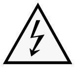
In the case of a REESS having high voltage capability, the symbol shown in Figure 4-1 shall be placed on or near the REESS. The symbol background shall be yellow, the bordering and the arrow shall be black. The symbol shall in addition be placed on all enclosures and barriers, which when removed expose live parts of high voltage circuits. This provision is optional for connectors for high voltage buses and does not apply to any of the following cases:
|
• Inspection • Review of Design |
Non Compliant | None |
References:
Glossary-7 the rechargeable electric energy storage…
Glossary-8 means the classification of an electric …
|
|||
| SysRS-36 | From Standard | EU 3/2014, Annex IV, 2.1.6.3 |
Cables for high voltage buses which are not located fully within enclosures shall be identified by having an outer covering with the colour orange. |
• Inspection • Review of Design |
Non Compliant | None |
References:
Glossary-8 means the classification of an electric …
|
|||
| SysRS-37 | From Standard | EU 3/2014, Annex IV, 2.2.1 |
Concerning protection against electrical shock which could arise from indirect contact, the exposed conductive parts, such as the conductive barrier and enclosure, shall be securely galvanically connected to the electrical chassis for instance by connections with electrical wire, ground cable, welds or by connections using bolts so that no dangerous electric potential can exist |
• Inspection • Review of Design |
Non Compliant | None | ||||
| SysRS-38 | From Standard | EU 3/2014, Annex IV, 2.2.2 |
The resistance between all exposed conductive parts and the electrical chassis shall be lower than 0,1 Ω when there is current flow of at least 0,2 A. This requirement is deemed as satisfied if the galvanic connection has been established by welding |
• Test |
Non Compliant | None | ||||
| SysRS-39 | From Standard | EU 3/2014, Annex IV, 2.2.3 |
In the case of vehicles intended to be connected to a grounded external electric power supply through a conductive connection, a device enabling the galvanic connection of the electrical chassis to the earth ground shall be provided. The device shall enable connection to the earth ground before external voltage is supplied to the vehicle and shall retain this connection until after the exterior voltage is removed from the vehicle. Compliance with these requirements may be demonstrated by using the connector specified by the vehicle manufacturer or by other analysis. A galvanic connection of the electrical chassis to the earth ground does not need to be provided in the following cases:
|
• Analysis • Test |
Non Compliant | None | ||||
| SysRS-40 | From Standard | EU 3/2014, Annex IV, 2.3.1 |
Concerning electric power trains consisting of separate DC or AC-buses: If AC buses and DC buses are galvanically isolated from each other, isolation resistance between all high voltage busses and the electrical chassis shall have a minimum value of 100 Ω/V of the working voltage for DC buses, and a minimum value of 500 Ω/V of the working voltage for AC buses. The measurements shall be conducted in accordance with the provisions laid down in Appendix 1 — Isolation resistance measurement method. |
• Test |
Non Compliant | None |
References:
Glossary-8 means the classification of an electric …
|
|||
| SysRS-41 | From Standard | EU 3/2014, Annex IV, 2.3.2 |
Concerning electric power train consisting of combined DC- and AC-buses: If AC high voltage buses and DC high voltage buses are galvanically connected isolation resistance between all high voltage busses and the electrical chassis shall have a minimum value of 500 Ω/V of the working voltage. However, if all AC high voltage buses are protected by one of the two following measures, isolation resistance between the high voltage bus and the electrical chassis shall have a minimum value of 100 Ω/V of the working voltage:
The isolation resistance between the high voltage bus and the electrical chassis may be demonstrated by calculation, measurement or a combination of both. The measurement shall be conducted according to Appendix 1 — Isolation resistance measurement method. |
• Test |
Non Compliant | None |
References:
Glossary-8 means the classification of an electric …
|
|||
| SysRS-42 | From Standard | EU 3/2014, Annex IV, 3.1 |
The REESS shall not overheat in case of excessive current or, if the REESS is prone to overheating due to excessive current, it shall be equipped with one or more protective devices such as fuses, circuit breakers and/or main contactors. When applicable, the vehicle manufacturer shall supply relevant data and analysis proving that overheating from excessive current is prevented without the use of protective devices. |
• Review of Design |
Non Compliant | None |
References:
Glossary-7 the rechargeable electric energy storage…
|
|||
| SysRS-43 | From Standard | EU 3/2014, Annex IV, 3.3 |
Electrolyte shall not spill from the vehicle when the vehicle is tilted in any direction, leaned left or right against the ground or even when the REESS is put upside-down. In case electrolyte is spilled from the REESS or its components due to other reasons, it shall not reach the driver nor any person on or around the vehicle during normal conditions of use, parked condition (i.e. also when the vehicle is parked on a slope) or any other normal functional operation. |
• Test • Review of Design |
Non Compliant | None |
References:
Glossary-7 the rechargeable electric energy storage…
|
|||
| SysRS-44 | From Standard | EU 3/2014, Annex IV, 3.4 |
The REESS and its components shall be installed in the vehicle in such a way so as to preclude the possibility of inadvertent or unintentional detachment or ejection of the REESS. The REESS and its components shall not be ejected when the vehicle is tilted in any direction, leaned left or right against the ground or even when the REESS is put upside-down |
• Review of Design |
Non Compliant | None |
References:
Glossary-7 the rechargeable electric energy storage…
|
|||
| SysRS-45 | From Standard | EU 3/2014, Annex IV, 4.1.1 |
At the start-up, including system power-on, in order to select the active driving possible mode, at least two deliberate and distinctive actions shall be performed by the driver. |
• Test • Review of Design |
Non Compliant | None | ||||
| SysRS-46 | From Standard | EU 3/2014, Annex IV, 4.1.2 |
At least a momentary indication shall be given to the rider when the vehicle is switched in active driving possible mode, however, this provision does not apply under conditions where an internal combustion engine provides directly or indirectly the vehicle’s propulsion power |
• Inspection • Review of Design |
Non Compliant | None | ||||
| SysRS-47 | From Standard | EU 3/2014, Annex IV, 4.1.3 |
When leaving the vehicle, the rider shall be informed by a signal (e.g. optical or audible signal) if the vehicle is still in the active driving possible mode. |
• Inspection • Review of Design |
Non Compliant | None | ||||
| SysRS-48 | From Standard | EU 3/2014, Annex IV, 4.1.4 |
If the on-board REESS can be externally charged by the driver, vehicle movement by its own propulsion system shall be impossible as long as the connector of the external electric power supply is physically connected to the vehicle inlet. Compliance with this requirement shall be demonstrated by using the connector specified by the vehicle manufacturer. |
• Test • Review of Design |
Non Compliant | None |
References:
Glossary-7 the rechargeable electric energy storage…
|
|||
| SysRS-49 | From Standard | EU 3/2014, Annex IV, 4.2.1 |
If the electric propulsion system is equipped with a means to automatically reduce the vehicle propulsion power (e.g. powertrain malfunction operating mode), significant reductions shall be indicated to the rider. |
• Test • Review of Design |
Non Compliant | None | ||||
| SysRS-50 | From Standard | EU 3/2014, Annex IV, 4.2.2 |
If the state of charge in the REESS has a significant impact on vehicle driving performance (i.e. acceleration and drivability, to be evaluated by the Technical Service together with the vehicle manufacturer), a low energy content shall be indicated to the rider by an obvious device (e.g. a visual or audible signal). The indication used for point 4.2.1 shall not be used for this purpose. |
• Test • Review of Design |
Non Compliant | None |
References:
Glossary-7 the rechargeable electric energy storage…
|
|||
| SysRS-51 | From Standard | EU 3/2014, Annex IV, 4.3 |
It shall not be possible to activate the vehicle reverse control function whilst the vehicle is in forward motion. |
• Test • Review of Design |
Non Compliant | None |